Lab 01-02: Quectel BG-96 Cellular Module from STM32 Host MCU
Lab Overview
In this lab, the user application (Mqtt demo app) shall run on a Host Microcontroller instead of the Laptop, as per the below setup.
Caveat
- This lab supports only non-secure element version of the IoT Discovery kit
- To add support for the secure element, it requires the FreeRTOS cellular HAL code compilation to be integrated with X-CUBE-AWS-2.0. X-CUBE-AWS-2.0 is pre-integrated with the FreeRTOS Kernel 202002 & the IoT libraries that comes with that release package. The procedure to integrate the latest version of the FreeRTOS kernel package/new IoT application components from FreeRTOS is currently not documented yet.
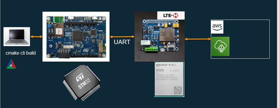
We will need to compile the FreeRTOS source code for the STM32 discovery board.(non-secure element version of the board)
Since the configuration files are specific to the target board, it is required to make appropriate changes to the board specific config_files directory.
A non-secure element version of the board is used for this testing. The secure element version, has a pre-integrated “FreeRTOS version” packaged as X-CUBE-AWS-2.0. This version could be compiled only using STM32Cube IDE. FreeRTOS cellular-HAL isn’t integrated yet to X-CUBE-AWS-2.0, which is using SBSFU. Hence non-secure element version (previous version) of the board is used.
Lab Setup
In this lab, we use the below setup
1) BG-96 shield board from here
2) STM32L4 Discovery Kit without Secure Element from [here] (https://www.st.com/en/evaluation-tools/b-l4s5i-iot01a.html)
There is no pre-requisite for the BG-96 shield board. Shield board from any vendor could be used. The only pre-requisite is that there need to be an “AT-cmd” port working over UART from the cellular Module.
Also check for the TTL voltage level compatibility with the STM32 IoT discovery board.
Do a manual test of the “AT-Cmd” Port from the PC/Laptop . This might require additional TTL to USB adaptor. Ensure compatibility with the TTL level(3.3V in this Test setup).
Connecting the BG-96 Shield Board to the STM32 IoT Discovery board
A UART connectivity (TX, RX, GND) is required for cellular module to the Host MCU communication. The BG-96 shield board that is used in this setup, has a dependency with the Pi Board for 3.3V. Hence the Bg-96 shield is connected to the Raspberry Pi. Else an equivalent External Power source could be used.
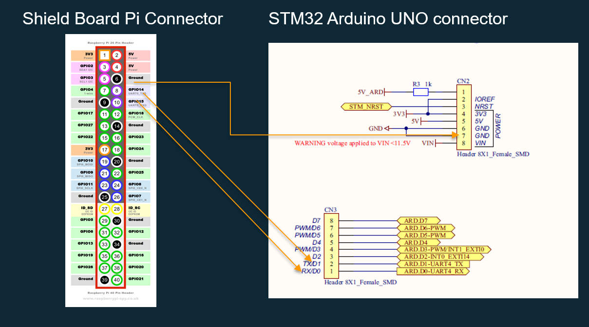
UART4 is used from STM32 for connecting the cellular module. Please check the UART pinout for TX,RX on the connector. It’ll be swapped for the shield boards to directly connect to the Host MCU board.
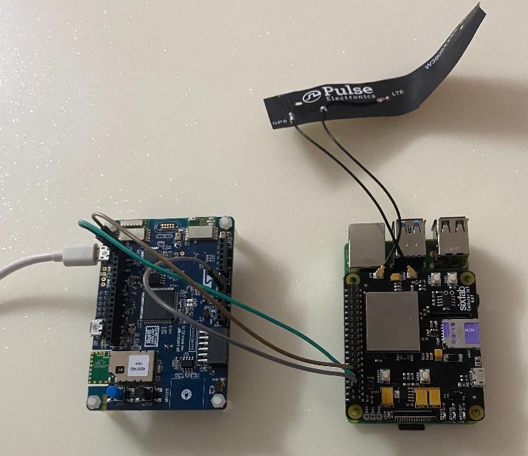
Prepare the setup per the below diagram
Steps for Configuration & Source Code Compilation for the Standard FreeRTOS MQTT Demo Application
IoT Device Certificate & Endpoint Configuration
If you have completed the steps from the previous lab, then there is no need to repeat the device certificate creation setup. The configuration is stored in the aws_clientcredential.h & aws_clientcredential_keys.h file. It’s adequate to do this setup only once.
Configuration File Update
Manually update all the configurations specificed in the “Cellular Network communication setup” onwards from here to the files in $FR_BASEDIR/vendors/st/boards/stm32l475_discovery/aws_demos/config_files/
Configurations specific to Cellular Connectivity to run MQTT Demo application from STM32 target
These are configurations which are specific to the STM32 target. Cellular connectivity requires more resources & the standard configuration from FreeRTOS demos need to be adapted.
$FR_BASEDIR/vendors/st/boards/stm32l475_discovery/aws_demos/config_files/aws_demo_config.h
#define democonfigDEMO_STACKSIZE ( configMINIMAL_STACK_SIZE * 12 )
$FR_BASEDIR\vendors/st/boards/stm32l475_discovery/aws_demos/config_files/FreeRTOSConfig.h
#define configMINIMAL_STACK_SIZE                     ( ( uint16_t ) 128 )
#define configTOTAL_HEAP_SIZE                        ( ( size_t ) ( 83 * 1024 ) )
Increase the publish retry interval in the file $FR_BASEDIR\demos/mqtt/iot_demo_mqtt.c
#define PUBLISH_RETRY_MS (5000)
Source Code Compilation Steps for Mqtt Demo Application
To configure the build use the below command
cmake -DVENDOR=st -DBOARD=stm32l475_discovery -DCOMPILER=arm-gcc -DSECURE_SOCKETS_CELLULAR=1 -DBOARD_HAS_CELLULAR=1 -B build-bg96-stm32 -GNinja
To Build use the below command
cmake --build build-bg96-stm32 --clean-first
Download the Application to the target
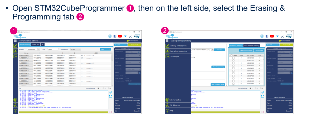
To download the firmware to the STM32 target, use the STM32Cube Programmer. link here
The start address should be set to 0x08000000 for programming
Download the aws_demos.elf located in the $FR_BASEDIR\build-bg96-stm32
Verify the results in the AWS IoT Core Management/Test Console
The TLS connection handshake time shall be relatively longer compared to the other modes of configuration.